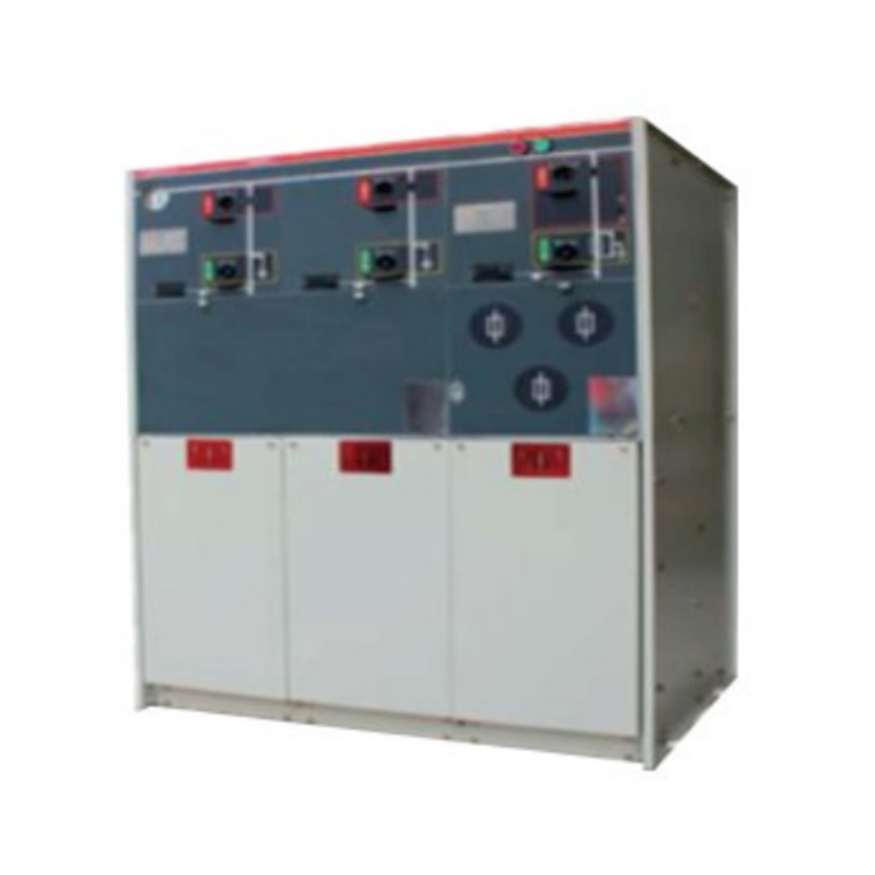
RM6-12/24 Gas Insulated Ring Main Unit Switchgea
Short Description:
RM6-12/24 Gas Insulated Ring Main Unit Switchgear adopts modular design,which fits the requirement of end user or network node by relying on perfectcombination of fixed and flexible expansion. It also meets the demand of various distribution switching stations, box-type substation and cable branch boxes. It has characteristics of compact structure, safe, reliable, long life and free maintenance. The switchgear includes an air tank welded by 3.0mm stainless steel, all live parts and switches are placed in it. Routine test shall be carried out for all elements/modules before the product leaves the factory. These elements/modules can be installed after delivery, and any special tool is not required.
Detail
Outline
RM6-12/24 Gas Insulated Ring Main Unit Switchgear adopts modular design,which fits the requirement of end user or network node by relying on perfectcombination of fixed and flexible expansion. It also meets the demand of various distribution switching stations, box-type substation and cable branch boxes. It has characteristics of compact structure, safe, reliable, long life and free maintenance. The switchgear includes an air tank welded by 3.0mm stainless steel, all live parts and switches are placed in it. Routine test shall be carried out for all elements/modules before the product leaves the factory. These elements/modules can be installed after delivery, and any special tool is not required.
Available module
·C Load break switch module
·De Cable connection module with earthing switch
·D Cable connection module without earthing switch
·F Load switch-fuse-combination unit module
·V Vacuum circuit breaker
·Be Bus ground module
M Meter module
·SL Bus section switch module(load switch)
*Sv Bus section switch module (vacuum circuit breaker)
Structural drawing of switchgear
1.Ring
2.Voltage indicator
3.Cable failure indictor
4.Pressure indicaton
5.Observation window for lower door
6.Analog circuit diagram
7.Integrated protection
8.Blown fuse indicator
9.Padlock device on the panel
10.Cover plate of cable chamber
11.Key lock(accessory)
12.Energy storage handle hole of circuit breaker
13.Load break switch handle hole(F unit energy storage)
14.Earthing switch handle hole
15.Isolating switch handle hole
16.Opening button(knob)
17.Closing button(knob)
18.Handle of cover plate of cable plate
19.Fuse room
Technical Parameter
| S/N | Name | Unit | Parameter | ||
| Load switch cabinet | Combined switchgear | Circuit breaker cabinet | |||
| 1 | Rated voltage | kV | 12/24 | ||
| 2 | Rated current | A | 630 | 125 | 630/1250 |
| 3 | Rated short-time withstand current | kA/s | 20/3,25/2 | / | 20/4,25/4,31.5/4 |
| 4 | Rated peak withstand current | kA | 50,63 | / | 50,63,80 |
| 5 | Rated short-circuit breaking current | kA | / | 31.5 | 20,25,31.5 |
| 6 | Rated short-circuit closing current | kA | 50,63 | 80 | 50,63,80 |
| 7 | Rated transfer current | A | 630 | 1700 | / |
| 8 | Rated closed loop breaking current | A | 100 | / | / |
| 9 | Full capacity breaking times | times | 5000 | / | 30 |
| 10 | Mechanical life | times | 5000 | 10000 | |
| 11 | 1min power frequency withstand voltage/phase to phase, to earth | kV | 42/50 | ||
| 12 | 1min power frequency withstand voltage/Isolation fracture | kV | 48/58 | ||
| 13 | Rated lighting impulse withstand voltage/phase to phase, to earth | kV | 75/125 | ||
| 14 | Rated lighting impulse withstand voltage/Isolation fracture | kV | 85/125 | ||
| 15 | Two circuit 1 min power frequency withstand voltage | kV | 2 | ||
