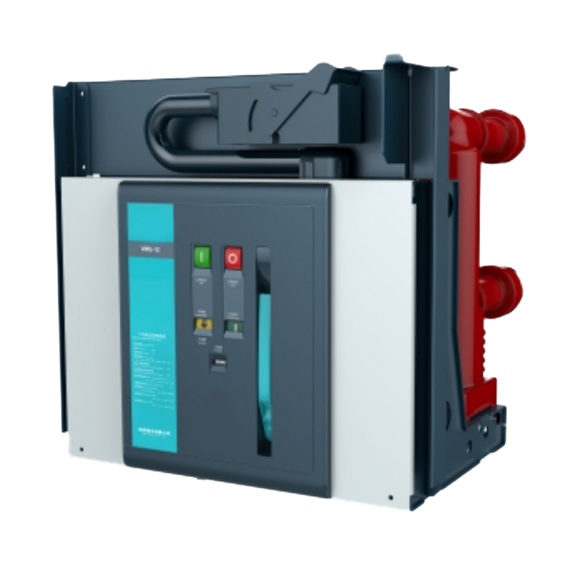
LBV 12kV Series Vacuum Circuit Breaker
Short Description:
LBV Series embedded pole vacuum circuit breakers are applicable to rating of 12kV,24kV, three-phase AC 50 or 60Hz indoor switchgear and serve as protection and control units for industrial and mining establishments and transformer substation equipment. With modular and independent-frame design for their spring operating mechanisms, LBV circuit breakers are available in the fixed and with draw able version.
Detail
Normal Service Condition
Altitude:≤1000m
Ambient temperature:
Maximum temperature:+40℃
Minimum temperature:-15℃
Average air temperature(24-h)+35℃
Ambient humidity:
Maximum average relative humidity
24 hours ≤95%
1 month ≤90%
Maximum water vapor pressure
24 hours ≤2.2kpa
1 month ≤1.5kpa
The influence of solar radiation may be neglected.
The ambient air is not significantly polluted by dust,smoke,corrosive and/or flammable gases,vapors or salt.
Vibration due to causes external to the switchgear and controlgear or earth tr-emors are negligible.
Special Service Condition
Special operating conditions are to be agreed on by the manufacturer and user,The manufacturer must be consulted in advance about each special
operating condition:
Site altitude over 1000m
-Allow for the reduction in the dielectric strength of the air.
-Or plateau type circuit breaker should be ordered,which shall meet corresponding insulation requirements.
Increased ambient temperature
-Current carrying capacity is reduced.
-Provide additional ventilation for heat dissipation.
Other considerations should be consulted with the manufacturer according to Section 2.2 in IEC 62271-1.
Applicable Standards
LBV Series vacuum circuit breakers comply with the latest version of IEC62271-100 and IEC62271-1 and have undergone the tests indicated below and guarantee the safety and reliability of the apparatus in service in any installation.
·Type tests:
Mechanical operation test
Dielectric test
Switching capacitor bank test
Temperature rise test
Short-circuit current breaking and making test
Short-time withstand current and peak withstand current test
Mechanical endurance test
No-load cable breaking and making test
Partial discharge test
·Routine test:
Switching synchronization
Open and close time
Bounce time
Insulation test of auxiliary and control circuits
Mechanical endurance test
Power-frequency withstand voltage test
Mechanical characteristic test
Main circuit measurement of resistance
Embedded Pole Design
LBV series vacuum circuit breakers embed vacuum interrupter in solid epoxy resin materials with higher creepage distance and electrical clearance, which is applicable for operation under harsh environment.
Use of epoxy resin as insulating medium also reduces pole centers distance,making vacuum circuit breakers and fitting switchgear compact.
Modular Operating Mechanism
Murge’s universal operating mechanism is a modular design that is common across all VMG circuit breaker frames,making circuit breaker family easy to work with. It is a self-contained functional unit and allows for fast and easy installation.The proven design ensures mechanical endurance up to 20,000 operating cycles.
Thanks to its modular design,material selection and limited number of moving parts,the mechanism assembly requires minimal inspection. The simplicity of the design reduces the energy required to operate it, minimizing system wear and the need for inspection.
Service Safety
Complete range of mechanical and electrical interlocks [available on request) are provided to prevent incorrect operations and to inspect the installations whilst guaranteeing maximum operator's safety Only when the circuit breaker and the earthing switch are in the breaking position can the circuit breaker truck be racked to the service position from the testing position.
The circuit breaker can be closed only when in the service/test position.
When the circuit breaker is closed,its truck cannot be racked,which can be racked in or out only when circuit breaker is in breaking condition.
The circuit breaker in closed position cannot be racked out from the service position to the test position, The circuit breaker cannot be closed while it is being racked in.
When the circuit breaker is closed, if the closing signal fails to be removed timely,the internal anti-trip control circuit will cut off the closing circuit to prevent multiple reclosing (optional).
If electric closing lockout is selected,the circuit breaker will be unable to be closed when the secondary circuit fails to provide power,or the power provided fails to meet the normal operation of the locking electromagnet (optional).
| Sr.No | Description | Unit | Parameter | |||||||
| 1 | Rated voltage | kV | 12 | |||||||
| 2 | Rated frequency | Hz | 50/60 | |||||||
| 3 | Rated insulation level | Power frequency Withstand voltage 1min(r.m.s) | kV | 42/48 | ||||||
| Lighting impulse Withstand voltage(peak) | kV | 72/85 | ||||||||
| 4 | Rated current | A | 630 | 630 | 1250 | 1600 | ||||
| 1250 | 1250 | 1600 | 2000 | |||||||
| 2000 | 2500 | |||||||||
| 2500 | 3150 | |||||||||
| 4000 | ||||||||||
| 5 | Rated short-circuit breaking current | kA | 20 | 25 | 31.5 | 40 | ||||
| 6 | Rated short-time withstand current | kA | 20 | 25 | 31.5 | 40 | ||||
| 7 | Rated short-circuit making current | kA | 50 | 63 | 80 | 100 | ||||
| 8 | Rated peak withstand current | kA | 50 | 63 | 80 | 100 | ||||
| 9 | Rated duration of short-circuit | s | 4 | |||||||
| 10 | Rated operating sequence | O-0.3s-CO-180s-CO | ||||||||
| 11 | Breaking times of rated short-circuit current | Times | O-180s-Co-180s-CO(40kA) | |||||||
| 12 | Mechanical endurance | Ops | 30/20 times(40kA) | |||||||
| 13 | Rated single capacitor bank breaking current | A | 20000 | |||||||
| 14 | Rated back-to-back capacitor bank breaking current | A | 630 | |||||||
| 15 | Double-earth fault breaking current | A | 27.4 | |||||||
| 16 | Allowable maximum contact erosion | mm | 3 | |||||||
| 17 | Clearance between open contacts | mm | 10±1 | |||||||
| 18 | Over stroke | mm | 3.5±0.5 | |||||||
| 19 | Non-simultaneity of 3-phase opening and closing | ms | ≤2 | |||||||
| 20 | Bounce duration of contact closing | ms | ≤2 | |||||||
| 21 | Average duration speed (instant breaking 6mm) | m/s | 1.1±0.2 | |||||||
| 22 | Average making speed | m/s | 0.8±0.2 | |||||||
| 23 | Closing time | ms | ≤100 | |||||||
| 24 | Break time | ms | ≤50 | |||||||
| 25 | Resistance of each phase main circuit | μΩ | 630A | ≤50 | ||||||
| 1250A | ≤45 | |||||||||
| 1600A~2000A | ≤35 | |||||||||
| ≥2500A | ≤25 | |||||||||
| 26 | Contact breaking bounce amplitude | mm | ≤2 | |||||||
| 27 | Rated operation voltage | Rated operating voltage(V) AC/DC | V V | 24 | 110 | 220 | ||||
| Scope of normal operation voltage | Closing:85%-110% rated voltage | |||||||||
| Opening:65%-120% rated voltage, in case the voltage is Lower than 30% rated voltage, opening operation is not allowed | ||||||||||
| 28 | Rated voltage of energy storage motor | V | AC110/220, DC110/220 | |||||||
